

Two-Way I2S Audio on ESP32-S3: I2S Microphone and I2S Speaker
A practical explanation of BCLK, WS, DIN, DOUT, full-duplex audio, sample rate, and buffers when building two-way I2S audio on ESP32-S3.
Share
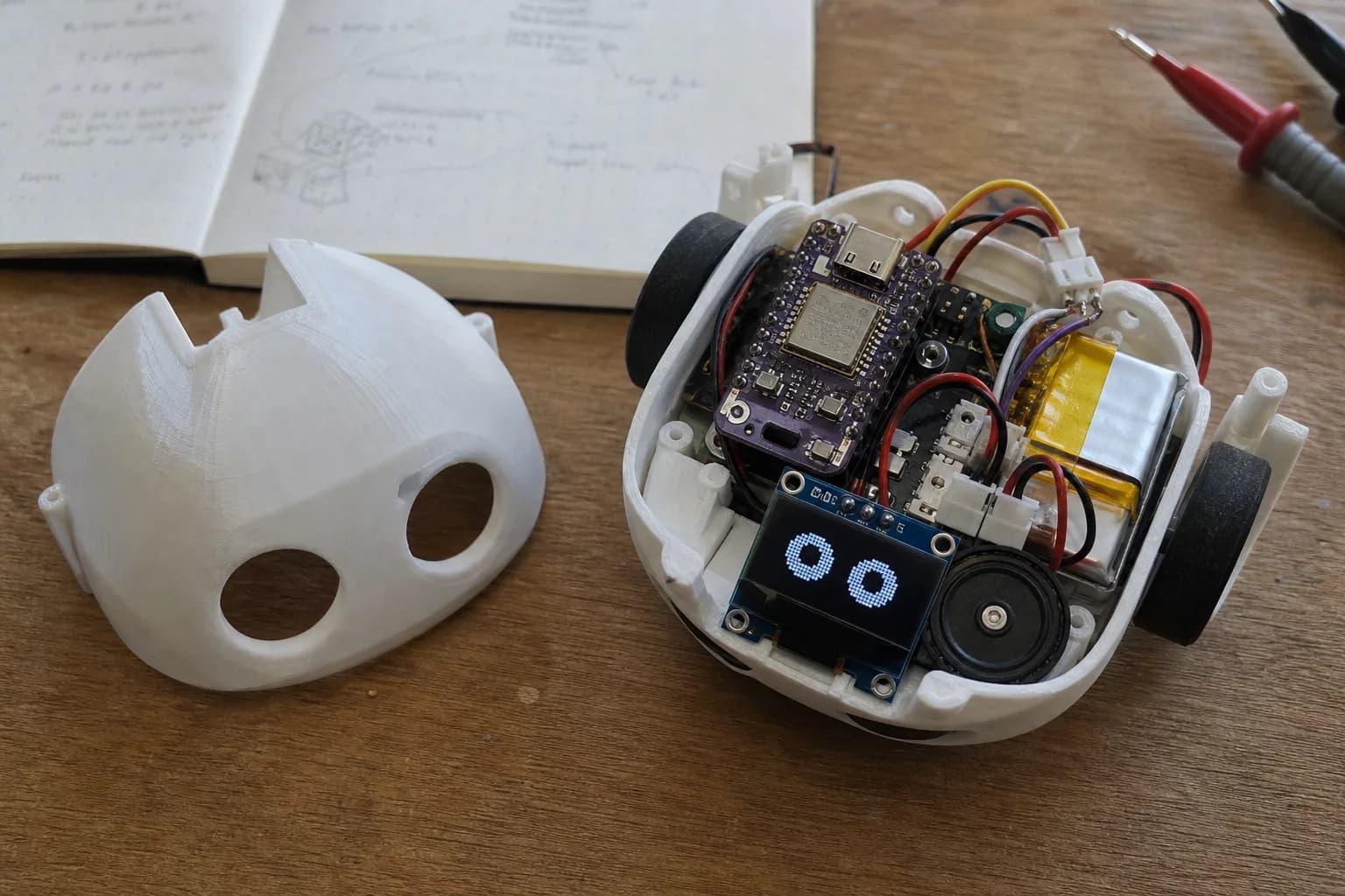
I will show you how I separate the input, output, clock, and buffer decisions before wiring an ESP32-S3 audio prototype.
When a small device needs to listen and play audio at the same time, I2S is usually cleaner than a hand-built analog path. On ESP32-S3, you can use an I2S MEMS microphone such as INMP441 for input and an I2S amplifier such as MAX98357A to drive a small speaker.
The first thing to understand is not the module name. It is the signal set: BCLK, WS, DIN, DOUT, sample rate, and buffers. Once those pieces are clear, GPIO planning and audio debugging become much less mysterious.
What I2S Is For
I2S is a synchronous serial protocol commonly used to move digital audio between chips. On ESP32-S3, the I2S peripheral can receive or transmit sample data through the ESP-IDF driver.
For a small robot or interactive device, the basic audio path looks like this:
- I2S microphone: sends audio data into ESP32-S3.
- ESP32-S3: reads the input buffer, processes it, or streams it.
- I2S amplifier: receives output audio data from ESP32-S3.
- Speaker: plays the amplified audio.
BCLK, WS, DIN, and DOUT
In standard I2S, the important lines are usually:
BCLK: bit clock. Each clock tick represents one data bit on the data line.WS: word select, also called LRCK. It marks which slot is active. In non-PDM mode, its frequency is usually equal to the sample rate.DIN: data entering ESP32-S3, for example from an I2S microphone.DOUT: data leaving ESP32-S3, for example going to an I2S amplifier.MCLK: master clock. Not every module needs it. Many common modules such as INMP441 and MAX98357A can work withBCLK,WS, and data.
DIN and DOUT can be confusing because the names depend on perspective. In this article, the perspective is ESP32-S3: DIN means data into ESP32-S3, and DOUT means data out of ESP32-S3.
Input with INMP441 or an I2S MEMS Microphone
An I2S microphone such as INMP441 commonly exposes:
SCKorBCLK: bit clock input.WS: word select input.SD: audio data output.L/R: left or right slot select.VDDandGND: power.
With ESP32-S3 acting as the master, the chip generates BCLK and WS. The microphone uses those clocks and sends audio data from its SD pin into a GPIO configured as the RX data input.
Output with MAX98357A and a Speaker
MAX98357A is a common I2S amplifier for small speakers. At the architecture level, it receives:
BCLK.WSorLRCLK.DIN, meaning audio data entering the amplifier.- A suitable power supply for the amplifier and speaker.
From ESP32-S3's point of view, playback data is on DOUT. That line connects to the DIN pin of the MAX98357A. The amplifier then drives a 4 ohm or 8 ohm speaker, depending on the module and power design.
What Full-Duplex Means
Full-duplex means the system can receive and transmit at the same time. For example, a robot can play a response sound while still listening for a stop command or environmental audio.
On ESP32-S3, each I2S controller has separate RX and TX channels. The ESP-IDF documentation notes that RX and TX channels can use separate clocks, slot configurations, and GPIO pins. In a practical two-way audio design, using the same sample rate and compatible data format on both directions is usually easier unless there is a strong reason to separate them.
A friendly starting point:
- RX: I2S microphone, mono, 16 kHz or 32 kHz.
- TX: I2S amplifier, mono/stereo depending on module, 16 kHz or 32 kHz.
- Sample width: start with 16-bit or 32-bit depending on the microphone format.
Choosing a Sample Rate
Sample rate is the number of audio samples per second for each slot. For voice UI, you do not always need 44.1 kHz or 48 kHz.
Practical suggestions:
- 16 kHz: good enough for wake word, speech commands, and basic voice input.
- 32 kHz: a better balance when output should sound more natural.
- 44.1 kHz or 48 kHz: more suitable for music or higher quality playback, but it costs more buffer memory and bandwidth.
For a small robot that plays short voice responses, 16 kHz or 32 kHz is usually easier to debug.
Buffers and DMA
I2S should not make the CPU copy every single sample manually. ESP-IDF uses DMA to move audio data in buffers. According to the Espressif documentation, DMA buffer size depends on frame count, slot count, and slot bit width.
The practical version:
- A smaller buffer reduces latency, but is easier to underrun or overrun if your task is late.
- A larger buffer is more stable, but adds latency.
- For two-way audio, RX and TX both need buffer space, so RAM must be planned early.
During the first prototype, choose a moderate buffer size, watch for underruns or timeouts, and tune from there. Do not start with the smallest possible buffer if your firmware is also running UI, Wi-Fi, or animation tasks.
Suggested Architecture
A compact architecture for ESP32-S3 + INMP441 + MAX98357A:
- ESP32-S3 acts as the I2S master.
- The I2S microphone receives
BCLKandWS, then sends data to ESP32-S3DIN. - MAX98357A receives
BCLK,WS, and data from ESP32-S3DOUT. - An RX task reads microphone data into a ring buffer.
- An audio processing task filters, routes, or streams data.
- A TX task feeds playback data to the amplifier.
If you need serious echo cancellation or voice processing, the architecture becomes more involved. But for a small robot or simple interactive device, this three-task model is a good starting point.
GPIO Planning Notes
- Assign I2S pins before lower-priority LEDs, buttons, or helper interrupts.
- Keep the microphone path away from the amplifier, speaker, and switching power section.
- Avoid pins already used by boot strap, flash, PSRAM, or USB on your specific ESP32-S3 module.
- Make data direction explicit in the schematic:
ESP32-S3 DOUT -> MAX98357A DIN,INMP441 SD -> ESP32-S3 DIN. - If
BCLKandWSare shared between microphone and amplifier, make sure the sample rate and slot format work for both sides.
Conclusion
Two-way I2S audio on ESP32-S3 becomes manageable once input, output, and buffers are separated clearly. With an INMP441 or another I2S MEMS microphone, a MAX98357A amplifier, and a small speaker, you can build a solid audio path for a desktop robot, voice UI, or embedded device with sound feedback. Start with a reasonable sample rate, stable buffers, and a clear GPIO plan before optimizing latency.
References
Related reading
Share
Keep exploring
Read next
Related articles
TinyML on ESP32: Running AI on the Device
How I run a small person-detection model on ESP32 with TensorFlow Lite Micro and ESP-NN, from memory limits to testing Espressif's example.
Extending Battery Life in an ESP32 Robot with a Display
Analyze battery life for an ESP32 robot with a display: backlight, Wi-Fi, audio, peripherals, sleep modes, wake sources, and runtime.
What Is a MEMS Microphone? From a Silicon Diaphragm to ESP32 Audio
Learn how MEMS microphones work, how analog, PDM, and I2S outputs differ, and how to avoid PCB, power, and acoustic-port mistakes.