

Complete Hardware Architecture for an ESP32-S3 Mochi Robot
A practical breakdown of ESP32-S3 Mochi Robot hardware: display, touch, I2S microphone, amplifier, speaker, battery, charging, and GPIO.
Share
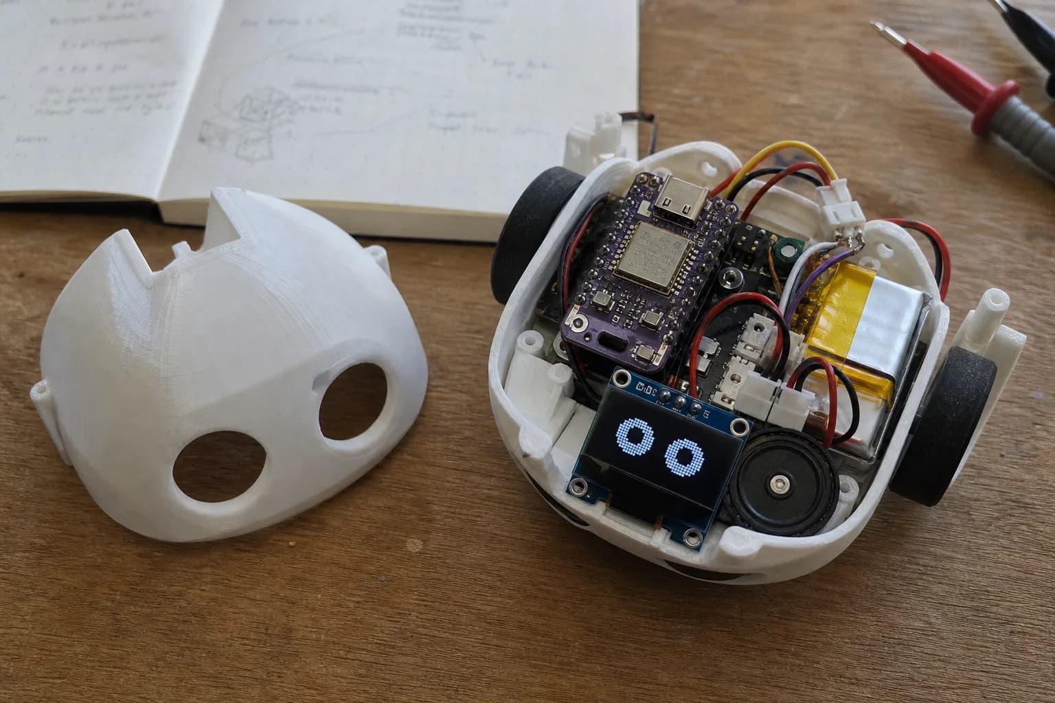
When Mochi moves beyond a simple prototype, choosing modules is only half the work. I find it more useful to split the system into clear blocks first: processing, display, touch, audio input, audio output, power, and debug.
ESP32-S3 is a good fit for a Mochi build with a color display, touch input, and basic audio. It provides useful peripherals for embedded UI work, including GPIO, I2C, I2S, SPI, LCD, and USB. Still, GPIO planning matters. A design can easily reach the point where the display works, but audio is noisy, touch has no interrupt pin left, or the board is difficult to debug once everything moves to a PCB.
High-Level Block Diagram
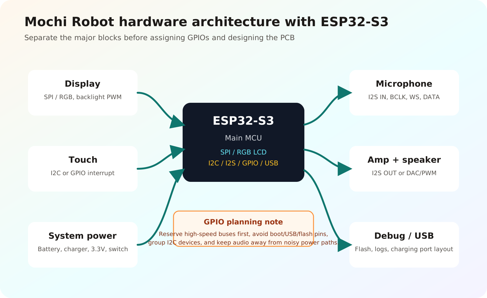
Suggested block diagram for an ESP32-S3 Mochi robot. This is a planning architecture, not a final schematic.
The diagram is not tied to one exact component list. Use it to see what each block needs, which buses are involved, and which interfaces you should reserve before spending the remaining GPIOs.
ESP32-S3 as the Main Controller
In this architecture, ESP32-S3 runs the main firmware, manages LVGL or a similar UI layer, reads touch input, receives audio from the microphone, sends audio to the amplifier, and tracks basic power state.
I treat ESP32-S3 as the coordinator of the whole product, not just a dev board with modules attached. When you plan the PCB, assign fast interfaces such as LCD, SPI, and I2S first. Slower enable pins, interrupts, buttons, and status LEDs can come later.
Display Block
Mochi needs a display for the face, expressions, battery state, connection state, and small menus. With ESP32-S3, common choices include:
- SPI LCD: easy to source as modules, fewer pins, suitable for small screens.
- RGB LCD: more pins, but useful when the UI needs smoother refresh or higher resolution.
- Small I2C OLED: simple, but limited if the robot needs colorful expressions or richer animation.
The ESP-IDF esp_lcd documentation describes LCDs through a control plane and a data plane. This way of thinking is useful for Mochi because it separates controller setup, pixel transfer, reset, backlight, and display power instead of treating the screen as one vague block.
Touch Block
Touch can be used for head taps, face interaction, or a small settings menu. Two simple approaches are common:
- A touch controller over I2C, possibly sharing the bus with other low-speed sensors.
- A basic capacitive touch sensor that outputs a digital signal to one GPIO input.
If you use an I2C touch controller, reserve an interrupt pin as well. It is tempting to say “I2C only needs two pins,” but an interrupt line lets firmware react to touch events without polling all the time.
I2S Microphone
If Mochi needs voice input, sound reactivity, or simple environment listening, an I2S microphone is cleaner than an analog microphone path. A typical I2S microphone needs BCLK, WS/LRCLK, and DATA.
On the PCB, keep the microphone away from switching regulators, speaker power traces, and the Wi-Fi antenna area. Audio is sensitive to noise, so the block diagram should already separate it from the power and amplifier sections.
Amplifier and Speaker
A speaker makes Mochi feel more responsive: confirmation sounds, state changes, or short voice clips. Two common implementation paths are:
- An I2S amplifier that receives digital audio directly from ESP32-S3.
- A small analog amplifier if the firmware only needs simple sounds through DAC/PWM or another audio source.
For a small desktop robot, speaker power does not need to be large. The more important part is power stability. A sudden audio peak should not dim the display or reset ESP32-S3.
Battery, Charging, and Power
A desktop Mochi robot will often use a single-cell LiPo or Li-ion battery. Treat the power section as its own design block:
- Battery.
- Charger.
- Battery protection if the charger module does not include it.
- Power switch.
- 3.3V regulator for ESP32-S3 and logic.
- Separate or filtered supply paths for the display and amplifier when needed.
Avoid powering everything by convenience alone. The display and amplifier can create changing loads, while ESP32-S3 still needs stable power when Wi-Fi, display refresh, and audio all run at the same time.
GPIO Planning Notes
A practical pin-assignment order:
- Reserve the display interface first, especially for RGB LCD or high-speed SPI.
- Reserve I2S microphone and I2S audio output pins.
- Reserve I2C for touch or secondary sensors.
- Keep room for USB, UART debug, boot mode, and flash/PSRAM requirements for the module you use.
- Assign buttons, interrupts, enable pins, LEDs, and secondary signals last.
There is no single GPIO table that fits every Mochi build. Each screen, ESP32-S3 module, and PCB form factor is different. The durable rule is simple: reserve important buses first, assign secondary signals later, and always check the exact module datasheet before drawing the PCB.
Suggested Prototype Configuration
For a first complete prototype, a balanced configuration could be:
- ESP32-S3 module with PSRAM if the UI needs smoother animation.
- 1.28-inch, 1.69-inch, or 2.0-inch SPI TFT display.
- I2C touch controller or a simple capacitive touch sensor.
- I2S microphone.
- Small I2S amplifier and a 4 ohm or 8 ohm speaker.
- Single-cell LiPo battery, USB-C charger, and a 3.3V regulator with enough current headroom.
- UART or USB debug access that remains reachable after assembly.
Once the firmware, UI, and audio path are stable, it makes sense to merge modules into a custom PCB. Doing that too early often turns every small wiring mistake into a harder hardware problem.
Conclusion
Plan an ESP32-S3 Mochi block by block from the beginning. Display, touch, microphone, amplifier, speaker, battery, charging, and power all affect GPIO assignment and PCB layout. That little bit of structure makes your prototype easier to debug and avoids painful board revisions later.
References
Related reading
Share
Keep exploring
Read next
Related articles
What Is a MEMS Microphone? From a Silicon Diaphragm to ESP32 Audio
Learn how MEMS microphones work, how analog, PDM, and I2S outputs differ, and how to avoid PCB, power, and acoustic-port mistakes.
ESP32-C3 or ESP32-S3: Which Chip for a Robot with a Screen and Audio?
Comparing ESP32-C3 and ESP32-S3 on GPIO, RAM, PSRAM, USB, I2S, and LVGL headroom, with a concrete recommendation for a basic Mochi build and a Mochi AI build.
ESP32 Battery Power Design: From USB-C Charging to the 3.3V Rail
Review an ESP32-S3 battery power path from USB-C and TP4056 charging to protection, load sharing, 3.3V regulation, and load budget.